My journey into asic repair

This thread I will update and document my own repairs to demonstrate it can be a good investment. I haven’t completed all of the theory test yet, I just need to make a video explaining how the hash boards of the S19 miners work before moving onto the next stage of the course.

All the equipment plus course cost $1600 usd.

The first thing I did with this equipment was a gentleman on this forum posted about turning the S19 90th J1-11 model into a 104th S19 J pro. I realised I had the equipment to do this, and bought one for $900 when the market price was about $1200 for a J pro, which runs well at 104TH and runs at 117TH for about 3800 watts. So I saved $300 there.

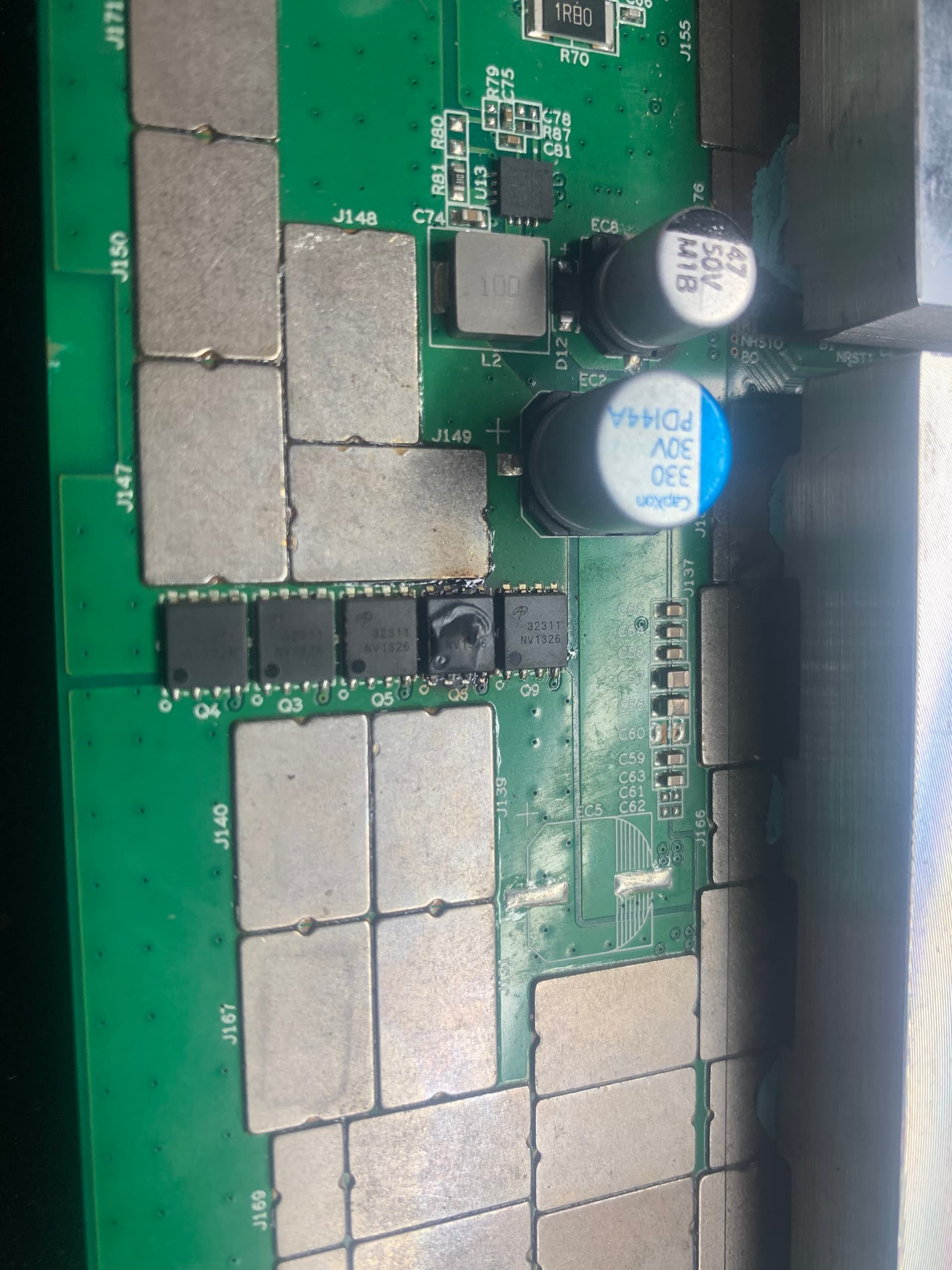
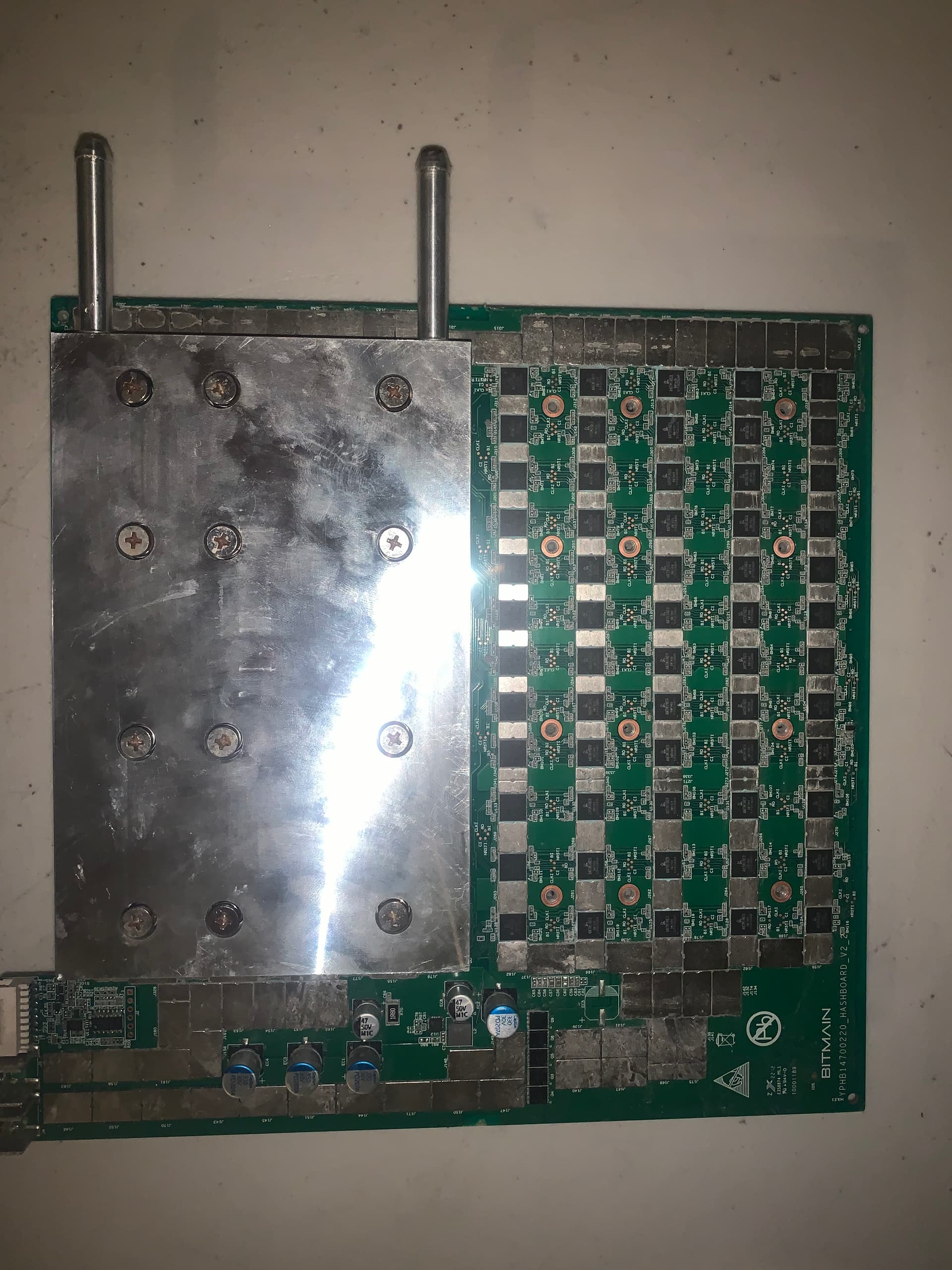
The other day a board on my L7 went down. The kernel log said it could only find 73/120 chips so I’m assuming the break on the chain is the 74th chip. Unfortunately my picobt is not updated and does not have the L7 board tester installed, so I’ve ordered the correct usb so I can plug it into my computer and update it, which will come next week. However in the mean time I took the water cooling plates off my L7 and found this

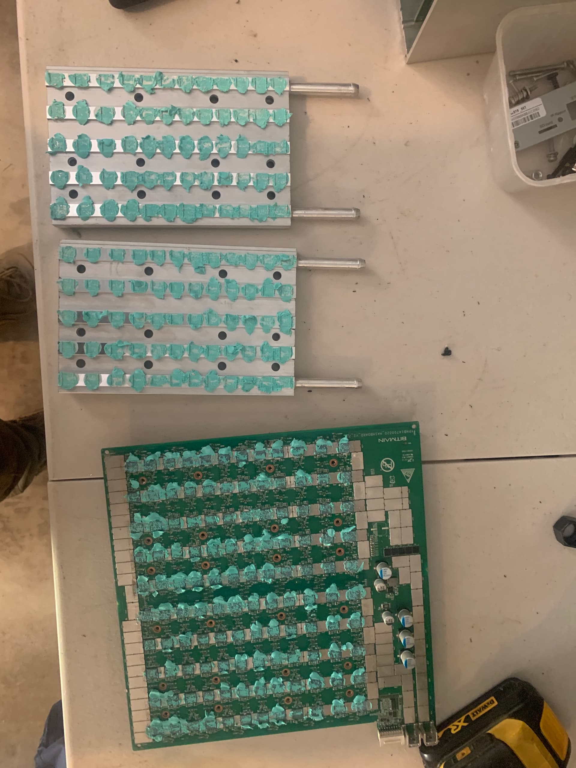
The thermal paste I’m pretty sure should not be bluey green, and I think that means I’ve got moisture in my miner. Because it is a water cooled miner, I have one side of my miner blocked off with the stock fans on the other side to take the heat out, and I have one side blocked off just to keep it clean. This is probably the issue having one side blocked off.

So I thought I’d replace the thermal grease and see if that will fix my issue while waiting for the usb so I can properly test my hashboard, unfortunately it is still giving an error on the 74th chip.

So I am ordering the BM1489 chip that my L7 uses, each chip costs $25 and the MOQ is 10. So that’s a $250 cost, however it’s important to note:

  • My L7 is out of warranty
    -there’s no local repairs and shipping each way is $200, as well as I think each board diagnostic plus repair is $100 from memory
    -I should only have to wait 7-10 days before I can fix it. Next time I should have no waiting time compared to a month wait at best sending it to the US or Asia
    -I am still running the miner with only 2/3 boards

So really this one repair alone is saving me $250, but can cover other repairs in future. If I get my shit together and finish the S19 course I could do the L7 course and offer local repairs to other L7 miners and make money back on the spare chips like that.

One thing I’ve learned just from this one time changing thermal paste is how it can spread over unwanted parts. I’m going to design and 3D print a cover that screws into the board while I’m cleaning the thermal paste that only leaves the chips showing but covers everything else so I can clean it easier. Each model I’d have to 3D print a different design, example L7 has 120 chips while J pro has 126 chips.

So at the moment I’ve saved $550/$1600 from this, and it has been fun learning and I’d recommend it if you’re in for the long haul

7 Likes

Yay! Another thread to read in the morning! Excited to see what you share next.

2 Likes

this is a top notch thread, super excited to follow along on your asic miner board repair journey

2 Likes

The blue green paste is the higher performance paste. It is 6.5 vs 4 of the pink.

As for the L7 vs the s19 as far as repairs go, they are virtually identical.

Check your clk with a multimeter before and after chip 74 and chip 75. You probably need to reflow chip 74. If that don’t work reseat chip 74. Finally if that don’t work replace chip 74. (If it’s chip 74 and not 75 that is the problem)

2 Likes

Thanks for that mate, in hindsight now I think about it if it was due to moisture then surely there would be some patches of the traditional paste colour. A mate I met on this forum who lives close has a busted L3 he said I can practice on so I can practice before doing the L7

L7 is more like the S19 than the L3 but they are all very similar architecture.

1 Like

I updated my Picobt to the firmware that reads the L7 boards and that was eventful, the first file I received I thought bricked the tester, the first screen appeared then it would go black and nothing. I contacted picobt freaking out and got a reply of “Don’t worry sir - please wait and we will send you a new file” they sent me a new file and it worked perfectly thank god!

So I tested the board and got 0 asic which we already knew, so I used the probe to try and identify what chip was not working. However, I could not get any chips to read. I made sure none of that plastic was covering the negative pole and still nothing. So my first thought was am I doing this properly? So I took out a working hashboard and tested it with the probe and it tested perfectly. While doing this I noticed the amps on my PSU was giving much lower amps on the broken board. So I tested the 23v circuit boost on the broken board and it gave a reading of 14v which is not normal. Once again to double check I was doing this properly I tested my working board and that gave a correct reading of 23v and assured me I did it correctly. I then contacted my teacher and told him the situation and told me the following

Indicates that the boost circuit is not working
Troubleshooting method:

  1. Check whether the resistance values of the sampling resistors R72 and R73 connected to the 3rd pin of U12 are normal.
  2. Check whether diode D11 is damaged.
  3. If there is no problem, replace U12

I checked the resistors and got nothing, I was confused and thought maybe my multimeter didn’t have the right gear and was going to ask my in-law if I could borrow his, because I did it also on the working hashboard. My teacher asked how it was going and I told him and he insisted I check again, which I did and got it to work, I must not have had the correct contact with the resistors and they are working normally, there’s no physical damage so I have to replace the U12 chip. I’d just like to thank my teacher Jack from Zeus for being patient with me while I couldn’t do the correct contact on 2 different boards lol.

For reference about the Picobt individual chip testing with the probe

23v boost testing

2 Likes

I finally got the time to replace the U12 chip on my L7 board, and my soldering iron died…so I got a new one a few days later and tried again, and replaced the U12 chip as my teacher said to do so. Before replacing this chip, the C70 chip was reading 14.2v when it should be reading 23v, and after replacing the chip it was still reading 14.2v, so the issue is not fixed. As far as I am aware I did the replacement correctly considering it is reading the same unless it was a bad connection before and also a bad connection now.

So now I am waiting on more advice from my teacher as what I should do. That part I replaced was like 70 cents so it’s not like I burnt money on it.

One thing I should consider is buying a whole L7 repair pack, which comes with 20 pieces of every possible part you can repair on a hashboard, however that’s $750 I think

My mate has a bad S19 J pro, all 3 boards are down, and I bought the repair pack for his miner version which cost $310 (except I only got 10 BC1362AI chips instead of 20) however if my S19 J pro goes down I can use those parts on mine also except for some of the chips even though we both have S19 J pro 104th he has BM1362AI chips while I have BM1362AC. Hopefully that’ll come on Friday so I can get some done on the weekend. Although I didn’t fix my L7 it was fun getting out and doing something on it and doing something new.

Edit: my teacher asked me to resolder it with no luck, and suggests I get some wire and tin from the 5th pin to R71 because he thinks the pad of the 5th pin looks no good so might not be getting a connection, and wire it like he’s drawn in the pic below, I’ll do that tomorrow

2 Likes

This is great! wish I had the money and resources, and overall hand ability to do this haha! Keep it up!

1 Like

So I feel like I’ve had lots of bad luck. Firstly, I have been unable to repair my L7 board yet. The U12 chip, I should be able to use my multimeter on the buzzer gear and get a reading on 3 pins, and can only get a reading on one pin, even without the chip there I should also be able to use the pads and get a reading, which I can do on my working L7 boards on just the pads. I also gave the board power and could not get a reading from the 2 pins/pads from my multi meter when they should be reading nearly 15v. I feel like there’s no power to those pads and I’m unsure if it’s possible to tin from the 15v booster to the pads/pins to give it power.

Anyway today I decided I would run my L7 with just 2 boards given how good scrypt mining profits are on powerpool and NiceHash. I hook it up and go inside to my computer to setup my pools and 3 minutes later my wife asks me why something in the garage smells like it’s burning. I go turn my L7 off and take it apart to investigate, and immediately I can see the heat sink that is on the other side of the MOS tubes has turned itself 90 degrees and is half off the pad. I then turn to the other side and I see this MOS tube melted. Keep in mind I have done nothing to this board.

I also saw the 3rd pin of the U12 chip looked burnt. I have a bag full of them so I replaced it which didn’t take long, and I thought I’d test it on my picobt tester because the board was fully functional before I turned it off. So I tested it and it ran perfectly, and the MOS tube did not smell or melt anymore. So it was nice knowing it was functioning, however I was not game to put it back in my L7 with the MOS tube like that, not worth the risk. So I need to order some more and fix it. Pretty frustrating and bizzare but I feel more confident in repairing this board then the other one. If I can’t repair the other board, I might scrap it for parts and try to sell the chips for at least 1/4 of the normal price which should be $600 towards buying a new board. I feel like I am improving on my soldering and doing a half decent job at least, hopefully my luck turns around

1 Like