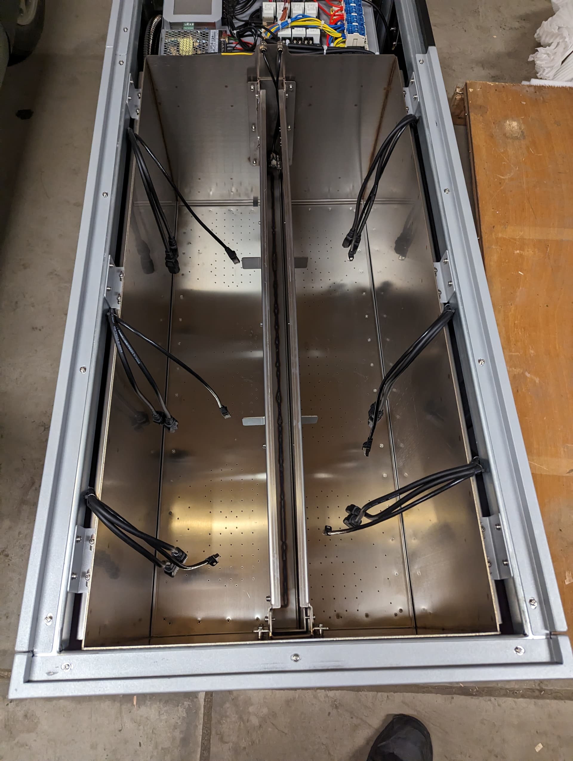
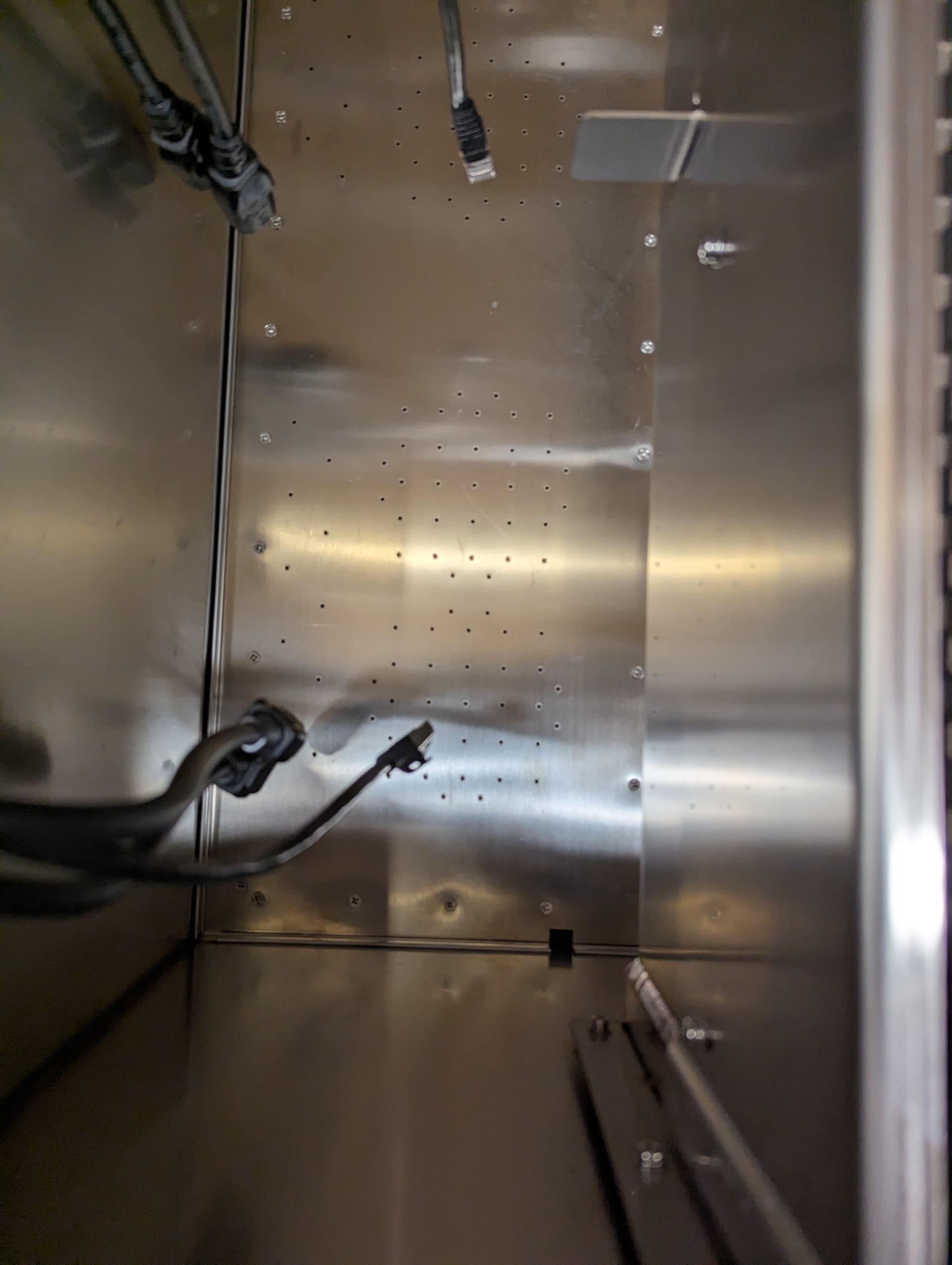
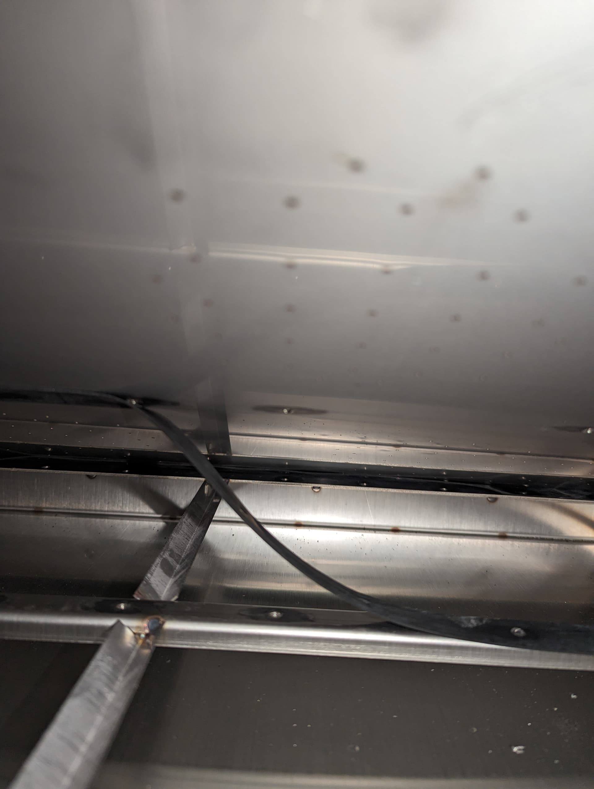
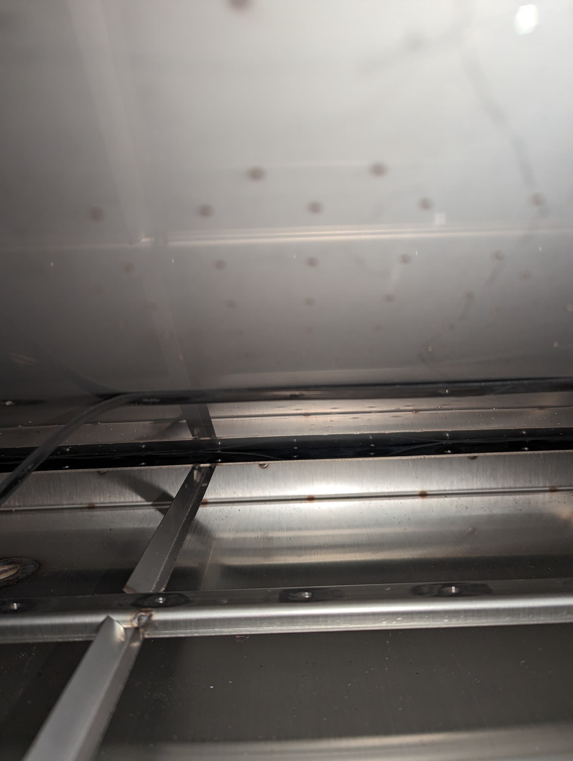
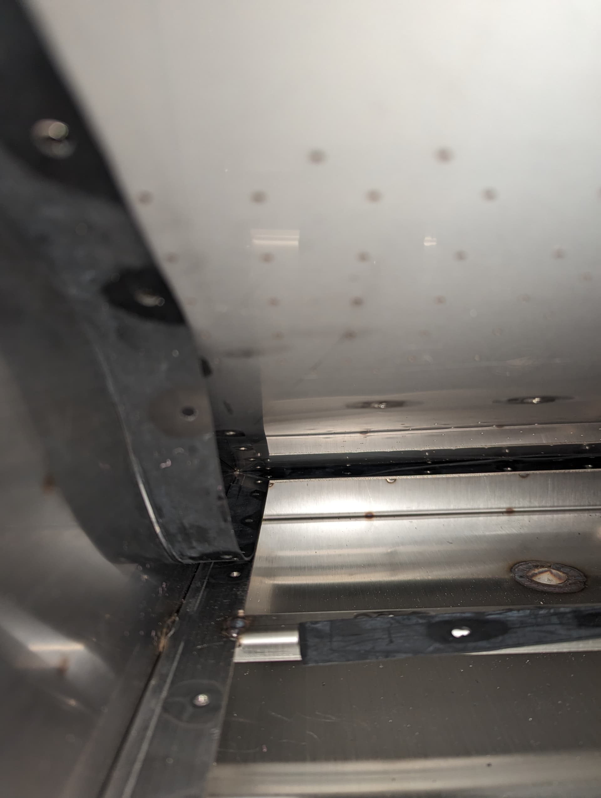
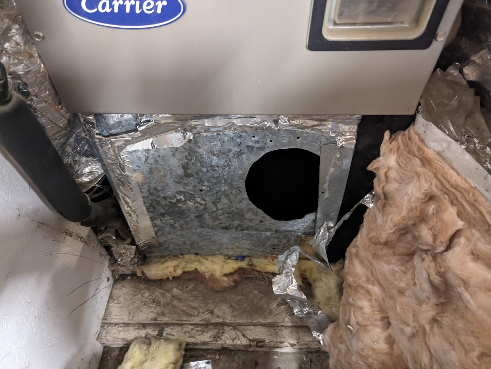
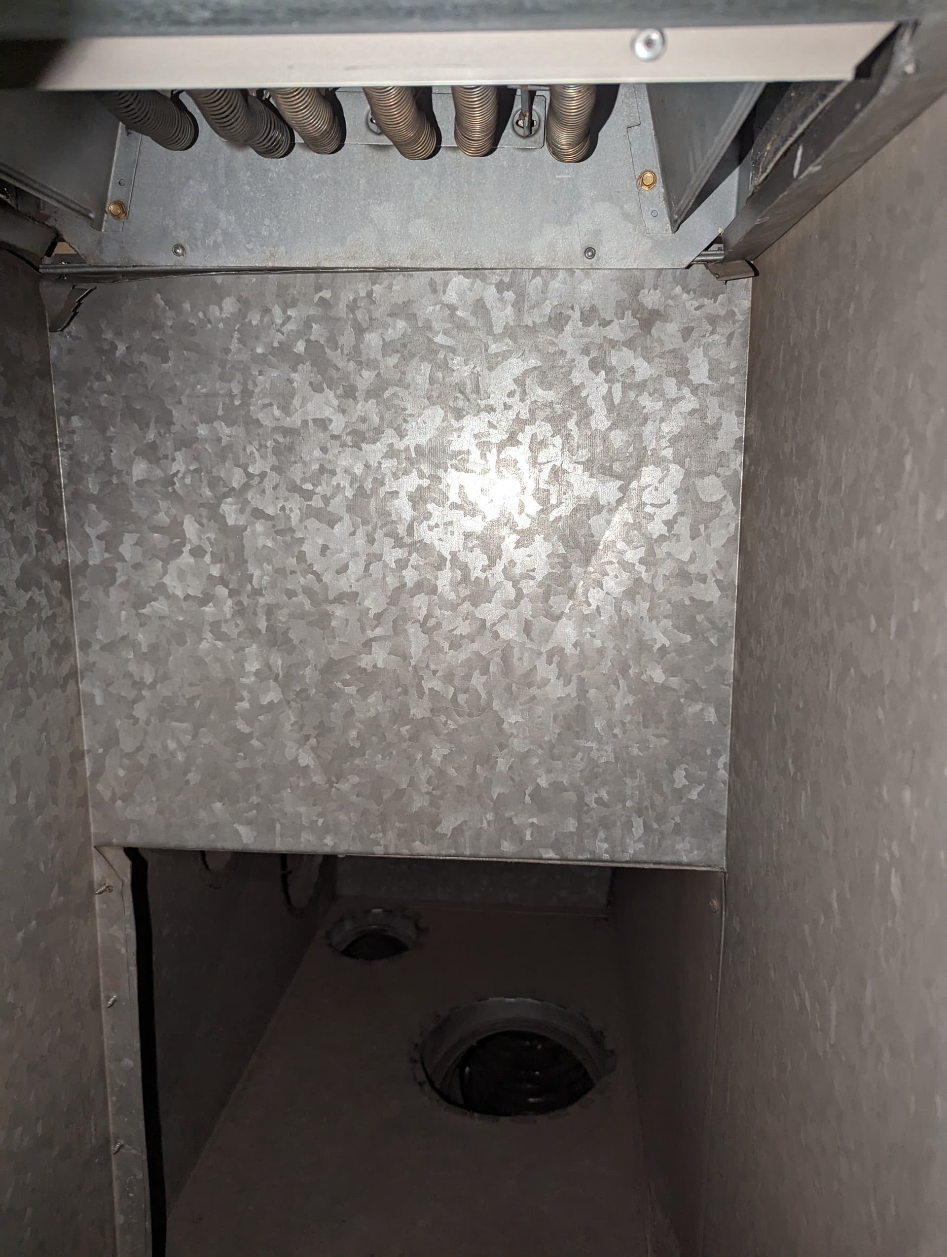
Immersion Cooling 4-6 Antminers with Fog Hashing's B6D.... Part 2

For part 1 of this journey, please find the original thread here:

This is a continuation of my journey of immersion cooling. I have acquired a B6D immersion tank from foghashing. I will be using their tank setup with their selected brazed plate cooler as well. I will post some pics in a moment.

1 Like

Most of these are from the last post of the part 1 thread, but they kick of this thread well.


1 Like

A couple more under the flow plate


1 Like

Iā€™ve had a little time to check some more things out. The subflow is simply pumped into this lower chamber below the flow plate. In my opinion, with sufficient flow there is nothing wrong with this. They have sealed the flow plate to actually make this ā€œchamberā€ which is really good to see. This makes sure the flow actually goes through the miners and no other way. There were quite a few screws to get to the point to get these shots. The magic will be if this chamber ends up being slightly pressurized. This will ensure even flow to all locations. The OTHER thing I REALLY like here is the flow comes down the middle and the miners are all on the outer part of this chamber. If you guys recall, I actually had negative flow in the asicshield right in front of the inlet. This will not be an issue here because there is not a miner in this spot. That is where the return trough is.

I have also taken this a step further and done some basic calculations.

1.5mm circle area = 1.767 mm squared
396 * 1.767 = 699.732

66 x 6 = 396 (total amount of holes for flow between all 6 miners)

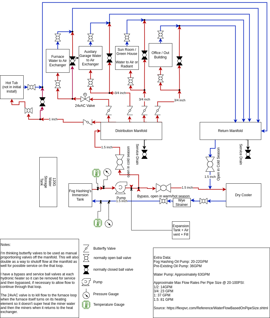
1" = 25.4mm = 506.71 mm squared (area of 1" inlet)

22GPM/6 = 3.67GPM / Miner (This is the estimated flow per miner). This is on par with what Iā€™ve gotten from those running large scale. Given this accuracy, we should be good here as well.

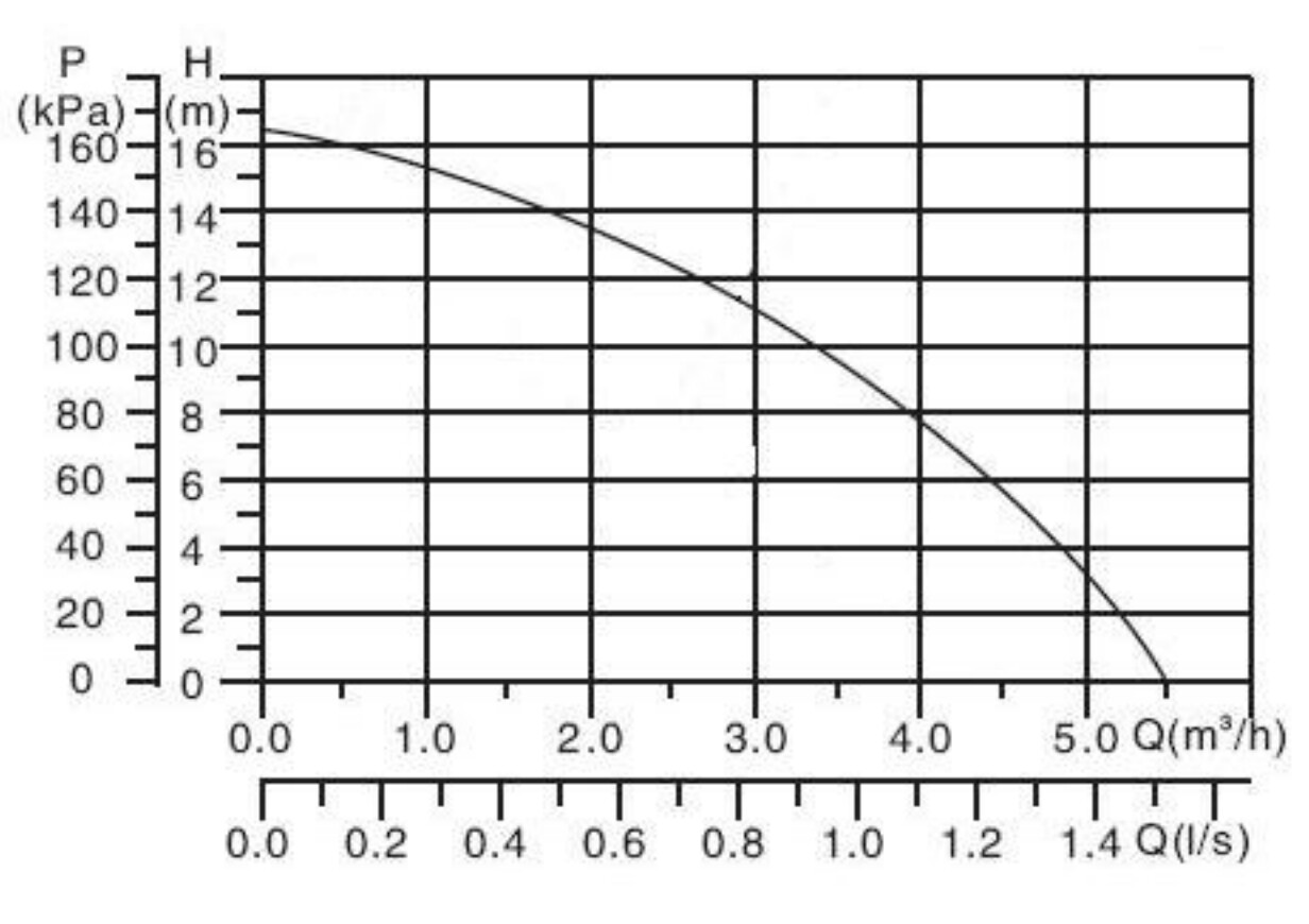
1.4 L/s is roughly 22GPM. It may be a little lower due to some losses and a slight pressure. Even hat about 35kPa (about 5psi) we are at 1.4 l/s. I think this number would be decently accurate.

While there is more area when combining all the small flow holes than there is via a 1" inlet, it may end up actually being very close in flow due to larger resistance through smaller holes. Once I get some fluid in this thing then Iā€™ll go ahead and do my ā€œflow checkā€ at all the locations. I donā€™t have a way to really measure the pressure, but this will give a good indication.

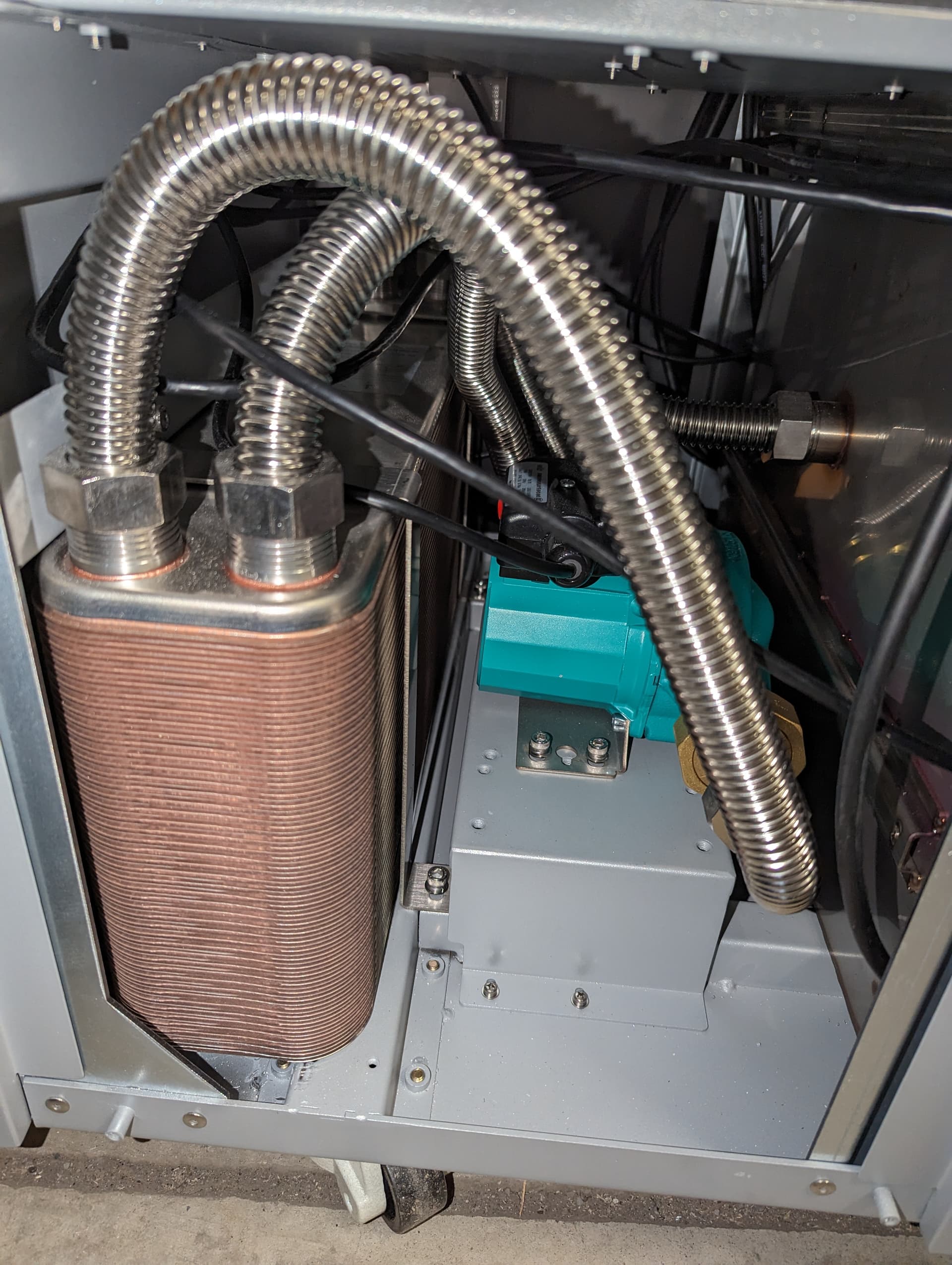
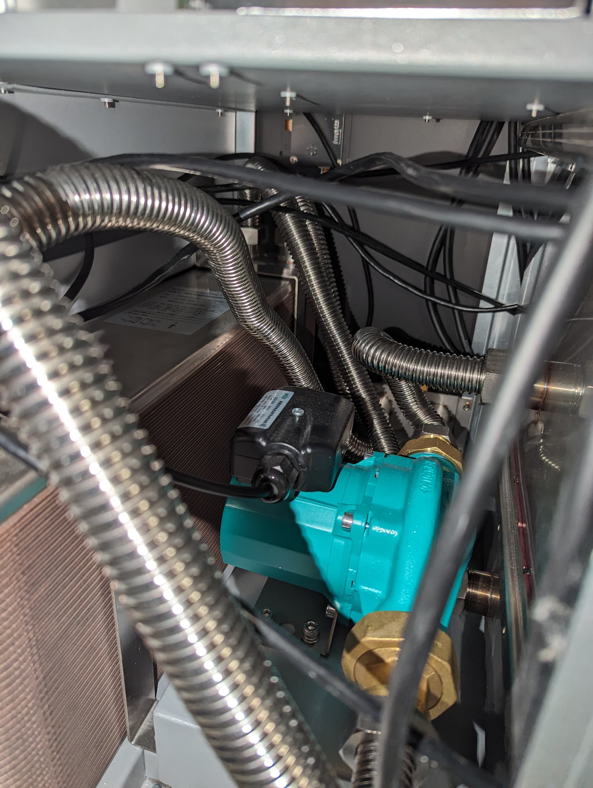
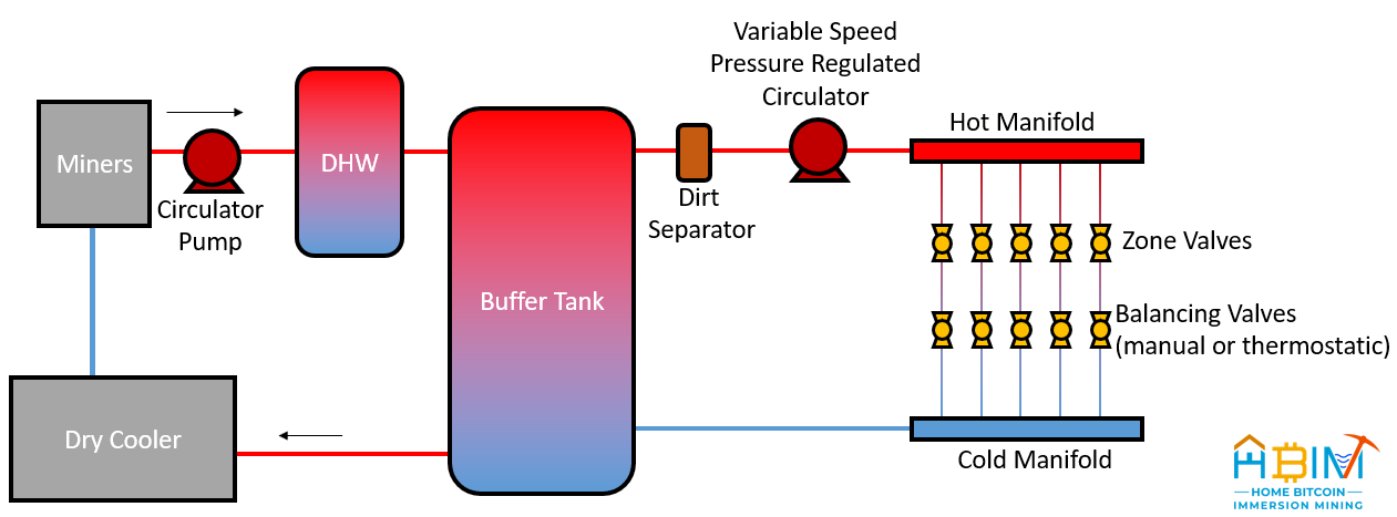
The metal tubes that were utilized between the heat exchanger, pump, and tank was a good choice.

At this juncture the only things I can see that could be improved would be putting a drain for the oil and a shutoff valve at the inlet and outlet of the tank. These are minimal and not necessary, but would make maintenance much easier if something need replaced or repaired.

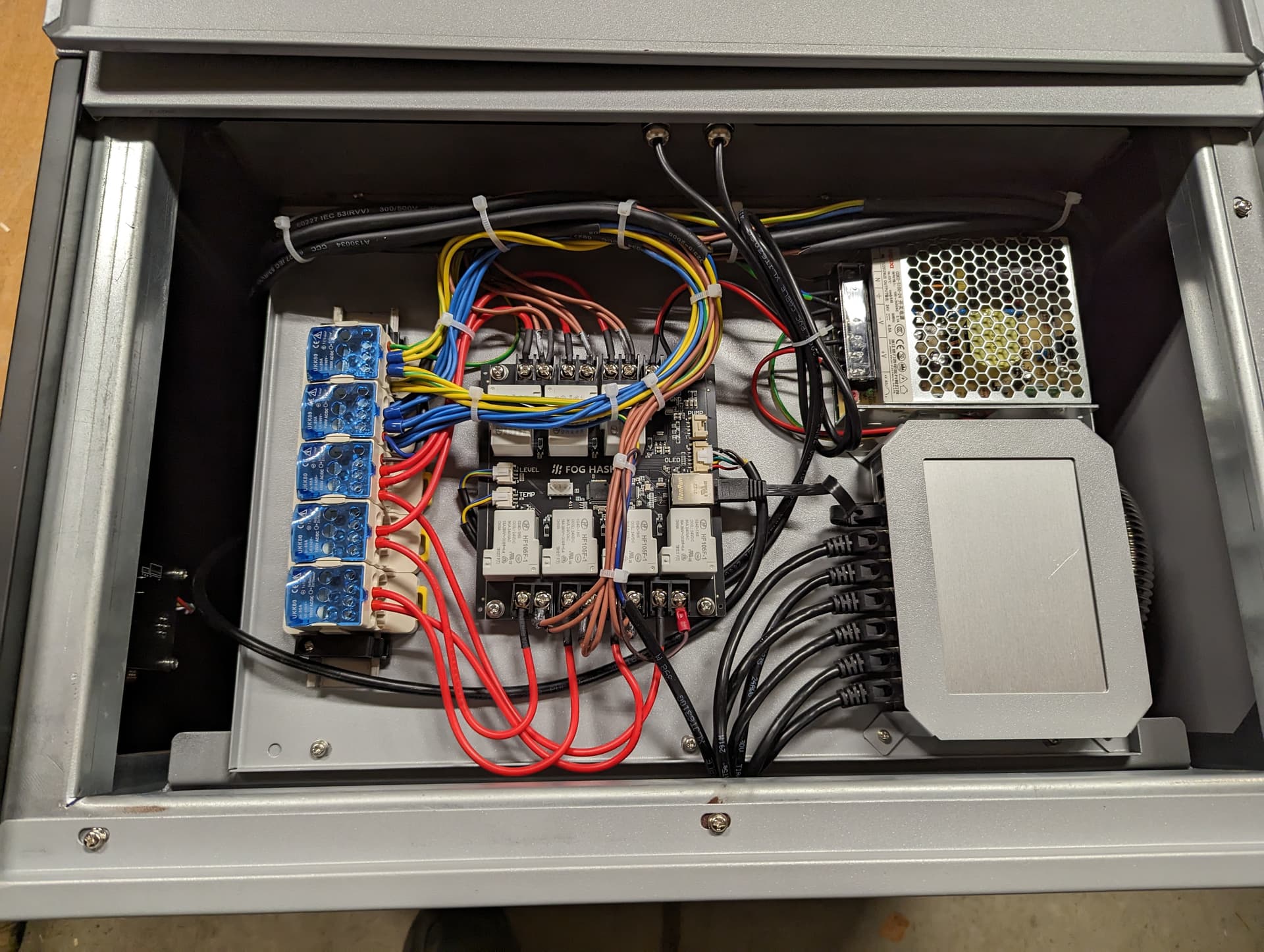
The cabling is done well and encased/sheathed where it needs to be. My only recommendation here would be something to discourage chaffing where the cables come into the tank where they plug into the miners.

These are both very minimal things.

1 Like

I am just working out some details for connectors and some design aspects prior to being able to install. I also reached out to someone on youtube for some input on reclamation design. Iā€™m hoping he hops in this thread.

I have a general rough draft for heat reclamation. Once I get it more finalized Iā€™ll draw it up in AutoCad or something similar. Nothing special and definitely lacking a lot of details right now.

In the cooler months, when Iā€™m utilizing heat, I would like to simply kill power to the fans on the dry cooler. I want fluid to still run through it so keep it from freezing. There is glycol in the water, but itā€™s a decently low %. If I need more heat then Iā€™ll get more miners. LOL. Iā€™m also looking possibly into the Epic control boards and their firmware to help control the miners better.

1 Like

My plan is to keep everything stainless steel, brass, and copper as to keep the lowest issues with galvanic reaction. These 3 materials are quite compatible.

Alrighty. I decided to give draw.io a try. I installed it in a docker and got this made up pretty quickly. Iā€™m still learning it, thatā€™s for sure. This definitely is missing lots of information, but at least makes it a little more clear and easier to read. Iā€™ll keep working on it and update.

edit: I anticipate the install, if done yourself, will pay for itself in 1-2 winters. Iā€™m in the pacific northwest. We get about 40" of snow a winter. Not a ton, but it does tend to live around 32 degrees for several months with colder periods in the teens and single digits here and there.

2 Likes

A minor update on the diagram. There are definitely a lot of things still omitted at this point.

A couple things to work through on this is the flow rates. 1.5" flows substantially more than 1". I put a little cheat sheet in the corner of the diagram. 1.5" manifolds arenā€™t terribly common and are insanely expensive if you can find them. I donā€™t need too many ports on my manifolds, so Iā€™m thinking of using SS ā€œTeesā€ to create a manifold so I donā€™t restrict flow and stress the pump. Something like the following and then use a coupler to join multiple of them together and then probably just do a 1.5"x1.5"x1" with the 1" going to the distribution. Then out of the Tee I can move to pex in whatever size I want.

One of the issues Iā€™m seeing is I think my water pump may be toooooo large for the heat exchanger in the foghashing unit. Iā€™m looking at a way to move my existing heat exchanger into the foghashing unit. Seeing that 1" may only flow 37GPM or so, I think it would create a lot of pressure trying to push that much through the 1" exchanger in the FH unit. My existing heat exchanger in the immersion tank has 1.5" connections for both oil and water.

I am trying to find a good location for my heat exchanger that will go into the furnace. I have a perfect spot, but I need to consider what happens when/if I need to kick on the actual/original furnace heat. Electrical coil heat would then super heat the minerā€™s heat exchanger if place in the outlet of the furnace, which is a more proper place to put it and the easiest place for me as well. Iā€™ve been talking with Bob and I think he is going to hop in this thread and provide some tips and insight as well.

We have talked about hooking a ā€œzone valveā€ to the inlet of the exchanger for the furnace and when the original furnace heat does kick on then it will shutoff flow to this water to air exchanger so that it isnā€™t pumping HOT water back to the miners.

Edit: I need to find a way to control the amount of flow down each distribution line. I donā€™t mind doing this all manually, but this way I can definitely control where the heat goes. For example, the priority is to not heat the garage, but rather the furnace and out building.

2 Likes

I am considering getting all exchangers from here. They offer a lifetime warranty :slight_smile: I would have to ship it back to them, but it would still be much cheaper than buying a new one. The exchanger linked is actually the one Iā€™m considering for the furnace.

1 Like

Here is the furnace setup. This is the outlet that feeds everything in the house. It measure a hair over 18" wide x roughly 22" deep. Iā€™m confirming some dimensions on the above heat exchanger as there are some discrepancies in the listing. I hope to simply bend some galvanized flashing to make an ā€œLā€ or angle iron in a sense. If I put this on the sides and the front lip then that should be plenty to support it. I may do a smaller version on the back side. I donā€™t want to block too much air flow in the back because that is where the direct air comes from. I donā€™t think this will inhibit air flow too much because I will be this entire area and the coils above where the air comes out is MAYBE 1/2 the area at best.


I may end up just going with these units for the hanging exchangers for the outbuilding and garage. I like that they have a filter on the back and a simple knob for area temperature. I know it can be only so accurate, but it gives a baseline to keep it at regardless.

https://www.amazon.com/dp/B0CB7ZJ5VJ/ref=sspa_dk_detail_5?pd_rd_i=B0CB7ZJ5VJ&pd_rd_w=kMCnH&content-id=amzn1.sym.0d1092dc-81bb-493f-8769-d5c802257e94&pf_rd_p=0d1092dc-81bb-493f-8769-d5c802257e94&pf_rd_r=KDRTM24JYCVDETWJJ12F&pd_rd_wg=wlxcQ&pd_rd_r=7f1fec6e-f2f5-43b5-8469-994e243008a4&s=hi&sp_csd=d2lkZ2V0TmFtZT1zcF9kZXRhaWwy&th=1

I will be utilizing oxygen barrier pex in 3/4 and 1"

1: https://www.supplyhouse.com/Bluefin-T100-300-OXY-1-Oxygen-Barrier-PEX-b-Tubing-300-ft-Coil
3/4: https://www.supplyhouse.com/Bluefin-T075-300-OXY-3-4-Oxygen-Barrier-PEX-b-Tubing-300-ft-Coil

I really would like to take 1" to the outbuilding, but there is 2" conduit stubbed out inside that is empty and I can only fit 2 x 3/4" through that. Thatā€™s going to have to do.

Iā€™m utilizing oxygen barrier because it help prevent the introduction of oxygen in a closed loop system. Oxygen is what inhibits corrosion/rust, so it is highly advised to go this route.

1 Like

Next iteration. Iā€™ve added the sizes of ā€œpipeā€ and service/bypass valves that I believe should probably be in every design. Hopefully this weekend Bob can chime in and tear it apart. lol. Iā€™ll keep working on it, but thatā€™s all for tonight.

Iā€™ve tried to make the pex piping large enough for even the smaller units so that I can flow enough through them to keep the machines cool even if I have to shut shut off flow to an exchanger for service/replacement.

2 Likes

I really hope people appreciate the time, effort, and dedication it takes to not only do what youā€™re doing, but also to meticulously document everything. Itā€™s pretty cool man.

4 Likes

Thanks! I love helping out! Threads also provide a good platform for input and improvement. I personally like forums over chat for most things because it maintains is place on the internet for future people to find. Anything I can do to help the home mining community continue to mine.

Wen vosksā€™ heat reclamation??? He can heat a massive greenhouse in the winter! I do hope his experience with immersion continues to be good. It really is the way forward. It definitely is not all perfected yet for us smaller guys, but itā€™s getting better with each immersion iteration.

4 Likes

Some more changes based on my thoughts of how things will work. We will hopefully see Bob tear it apart this weekend. LOL.

I still need to do some thinking about the configuration in and around the flow to the drycooler and though the manifolds for the 1.5". Thatā€™s still a work in progress for sure. Iā€™ve also been quite busy the last couple days. Iā€™ll post a couple pics to show what Iā€™ve been up to.

1 Like

My back is a little sore, but itā€™s 90% done. I just have to finish up the ends. Iā€™m also running water in this ditch that I needed to finish the ā€œhome runā€ on for supplying it to some hydrants on the property. The trench is near 24" everywhere. I have decided to forgo the snow melt aspect for the time being. I can add this on later if I need to and have enough extra heat.


1 Like

Ban him. @killtheplanet

1 Like

Hi All,

This is a really cool buildā€¦love to see bitcoin heat used in real homes!

I had some time to give this a little thought. This might be a fairly radical thing to do at this point, but a different architecture/design might simplify things a bit. Hereā€™s a rough idea based on using a buffer tank. This would give you hydraulic separation between the flow though the dry cooler and flow through the other uses of the heat. I think this also might operate better in the ā€˜in betweenā€™ seasons where you might want to use the heatā€¦but not enough to stop using the dry cooler. Thoughts?

Thinking about this a little moreā€¦you could also use a HX between the loops. Thereā€™s no thermal storage, but it might be cheaper and more compact:

another idea is very similar to what youā€™ve got above. You can use what is called ā€œclosely spaced teesā€ for hydraulic separation. No thermal storage here either, but its super cheap (two fittings) and gives you lots of flexibility for design:

1 Like

Thanks for the input! I suppose I should have included the brazed plate heat exchanger on the drawing :slight_smile:

At this juncture nothing has been purchased with respect to the manifolds, valves, fittings, etcā€¦

This would resemble the closest to what Iā€™m after, except my dry cooler is on the water side. Iā€™ll make some changes on my drawing and update it here.

I think manual valves would be good. The oil temps can vary a lot. ie, in the summer they would be upper 20s (C) and on the hottest days they would reach 51C, but most of the time during the day they would sit in the 40s. This is all outlet oil temps. On the original tank, there is not an inlet temp so I donā€™t have that info.

A couple questions on design, I suppose would be:

  1. Am I going overboard by putting ball valves on the inlet/outlet of each heat exchanger and also with a bypass? My thoughts with the bypass is I can still flow fluid through the system as the water pump puts out a lot of flow, about 63GPM, and I may need to still pass fluid through a zone so too much pressure doesnā€™t build up in the other zones.

  2. For the zone/balancing valves, could I simply use a butterfly valve to double as a shutoff if necessary, but mostly to control the flow? Is this the best option or should I break it out into a ball valve and either a butterfly or different type of manual balancing valve? I think this is definitely the most pressing question that is holding up ordering parts.